Connecting an Apple and your host computer through serial ports can take several forms. This section details:
In addition, using the modem port of a Mac LC, it is possible to run ADTPro on a Apple IIe card.
Once you have your computers connected, you may move on to bootstrapping.
The cable to connect a Super Serial card to your host computer's serial or USB port can either be straight-through or of the null modem variety. There is a jumper block on the Super Serial card that will take care of signal switching for you if you have one or the other and need to switch.
If you would like to purchase a ready-made serial cable, ADTPro-compatible cables are available here.
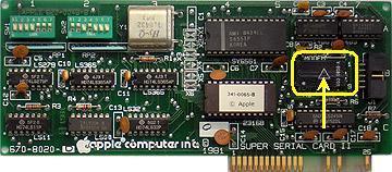
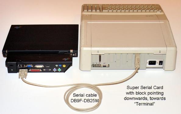
To connect with a straight-through cable, set the Super Serial card's block to point downwards toward the word "Terminal," as in this picture:
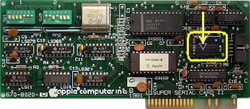
To connect with a null-modem cable, set the Super Serial card's block to point upwards toward the word "Modem," as in this picture:
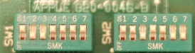
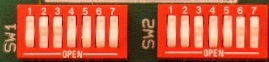
Once ADTPro is up and running, it sets the card's configuration switches through software. But to ensure trouble-free operation in the initial bootstrap step, you should set the switches like so:
SW1: 1001111 SW2: 1101100
Where 0 means off, down, or open, and 1 means on, up, or closed. Super Serial cards came with (at least) two different kinds of jumper blocks. One had little rocker switches, and the other had little sliders. Here are two examples with switches in the correct position:
Configured as a "terminal" (with the arrow on the jumper block pointing downwards on the SSC card), a connection with a straight-through serial cable would look like this:
Once you have your computers connected, you may move on to bootstrapping.
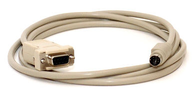
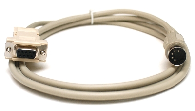
You will need a serial cable setup that ultimately connects the round, 8-pin mini-DIN modem connector of your IIgs or IIc+ to the serial or USB port of your host computer - and also performs a null-modem function in between. If you would like to purchase a null modem cable that is ready to use, click here. They look like this:
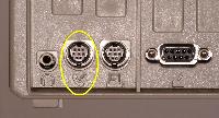
There are two 8-pin mini-DIN connectors on the backs of IIgs and IIc+ computers. One has the icon of a telephone, the other has an icon of a printer. Be sure you are plugging into the telephone (modem) one. The IIc+ plug is located here:
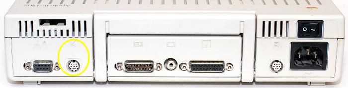
And the IIgs connector is located here:
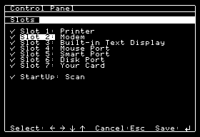
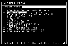
For the IIgs, you will also need to verify a couple of things in the control panel. You bring up the IIgs control panel with the key sequence Control-OpenApple-Escape.
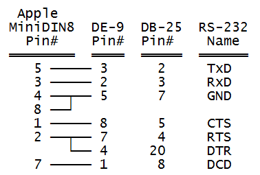
If you are building your own cable, this is the pinout to use. It describes the round "MiniDIN8" male connector looking into the cable at the pins:

A single-cable null-modem is wired like this (Apple would call this a "Printer" cable):
Once you have your computers connected, you may move on to bootstrapping.
You will need a serial cable setup that ultimately connects the round, 5-pin DIN modem connector of your IIc, Laser 128, or Franklin Ace 500 to the serial or USB port of your host computer - and also performs a null-modem function in between. If you would like to purchase a null modem that is ready to use, click here. They look like this:
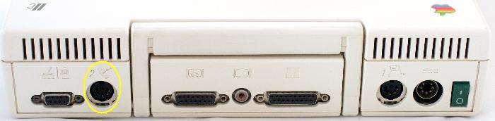
There are two 5-pin DIN connectors on the backs of IIc computers and compatibles. One has the icon of a telephone, the other has an icon of a printer. Be sure you are plugging into the telephone (modem) one, on the far left as you look at the back of the IIc:
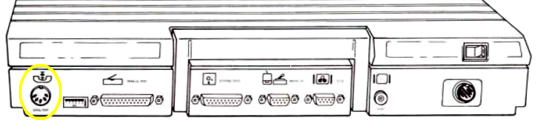
On the Laser 128, it's on the right side of the case, but just to the left of the printer port:
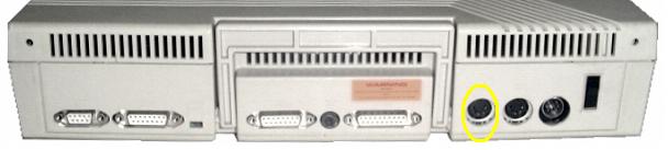
The modem port on the Franklin Ace 500 is the left-most connector:
If you are wiring a null-modem yourself, the following is the pinout to use. This pinout describes the round male connector looking into the cable at the pins. Note that this is numbered using Apple's (not DIN's!) standard:

A single-cable null-modem is wired like this (Apple would call this a "Printer" cable):
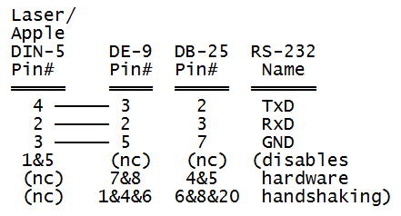
Within the DIN-5 shell, tie together pins: 1&5
If using DE-9: Within the DE-9 shell, tie together pins: 1&4&6 and 7&8
Or, if using DB-25: Within the DB-25 shell, tie together pins: 6&8&20 and 4&5
This null modem cable ties all the handshaking lines together at the host end and at the Apple end. This effectively disables hardware handshaking.
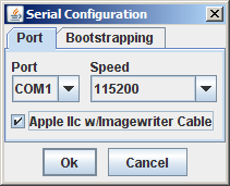
There are two pinouts for a single-cable null-modem that will work with ADTPro: an "Imagewriter I" cable (one that does some amount of "hardware handshaking") and one without. The Apple IIc's hardware handshaking tends to be problematic and non-standard, so we're only discussing the non-hardware handshaking cable here. If you happen to have an Imagewriter I cable, you will need to tick the "Apple IIc w/Imagewrite Cable" checkbox in the serial config dialog box, brought up from the File->Serial Configuration menu item:
The Laser 128 and Franklin Ace 500 will not work with the Imagewriter I cable.
Note that the original IIc motherboard was not supposed to be able to operate the serial port accurately at speeds higher than 300 baud, but in practice they work fine at all speeds. If you're curious, you may check the revision of your IIc by checking memory location 64447:
Once you have your computers connected, you may move on to bootstrapping.
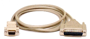
You will need a serial cable setup that ultimately connects the connector labeled "PORT C" on the back of your Apple /// to the serial or USB port of your host computer - and also performs a null-modem function in between. If you would like to purchase a null modem cable that is ready to use, click here. They look like this:
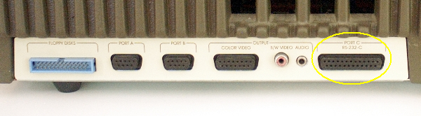
The RS-232-C port on the back of the Apple /// has the same physical connector as the Super Serial card: a female DB-25. But unlike the SSC, it can't be configured to use a null modem or not: it is hardwired to require one. At the back of the Apple ///, connect your null modem to the RS-232-C connector (also labeled "PORT C"), which looks like this:
If you are building your own cable, the pinout for a single-cable null-modem is below:
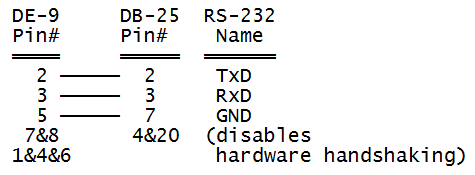
Within the DE-9 shell, tie together pins: 1&4&6 and 7&8
Within the DB-25 shell, tie together pins: 4&20
Once you have your computers connected, you may move on to bootstrapping.
Several manufacturers make different types of USB to serial adapters. These types of devices will work fine with ADTPro. When you use one, you will also need to install the appropriate device driver that connects your host operating system to the USB adapter.
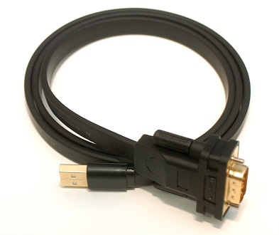
If you would like to purchase one that is compatible with both Windows and OSX operating systems, I offer one for sale here that works with the null modem cables shown above. They look like this:
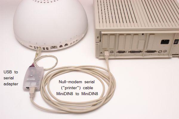
You will need to connect everything up with the right combination of cables, of course. Here is an example of a Keyspan USB-to-8-pin mini-DIN adapter connected to a IIgs:
Each manufacturer will include a software driver that will provide the "glue" between the computer and the adapter. For example, the Keyspan adapters come with a piece of software they call "Keyspan Serial Assistant:"
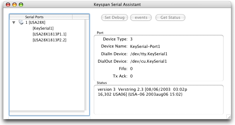
This software will tell you some details about the serial adapter, the name it chooses to call itself, and so on. In our case, we can see that the adapter has chosen port names like "KeySerial1," "USA28X1813P1.1," and "USA28X1813P2.2". Since this adapter happens to have two ports on it, you see suffixes of ".1" and ".2." They will correspond to whichever port (on the adapter itself) you are plugging your serial cable into.
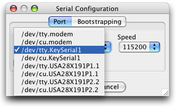
At the ADTPro server software end, should see those names repeated in the serial configuration dialog box (which comes up with the File->Serial Configuration menu item). In Keyspan's case, you will see a prefix of "tty" and "cu" added to each port name. ADTPro seems to be able to function normally using either flavor.
An adapter with a Prolific or FTDI chipset, for example, would populate the dialog box items like "usbserial":
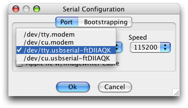
Once connected, ADTPro will be able to operate normally over the USB connection, including bare metal bootstrapping operations.